By Ron Wanttaja
May 2020
“We were off to fight the Hun
Though hardly anyone
Had ever read of battle,
much less seen a Lewis Gun…”
- From "Billy Bishop Goes to War"
Download Solidworks Construction Files (warning: 60 Meg ZIP file).
Introduction
 Maybe you’ve got a replica World War 1 Nieuport
that need a machine gun on the upper wing for that final
touch. Maybe you’re a Great War re-enactor, needing
machine gun for your infantry squad. Or maybe you’re a
Star Wars Cosplayer, who needs a blaster for a heavy-weapons
unit.
Maybe you’ve got a replica World War 1 Nieuport
that need a machine gun on the upper wing for that final
touch. Maybe you’re a Great War re-enactor, needing
machine gun for your infantry squad. Or maybe you’re a
Star Wars Cosplayer, who needs a blaster for a heavy-weapons
unit.
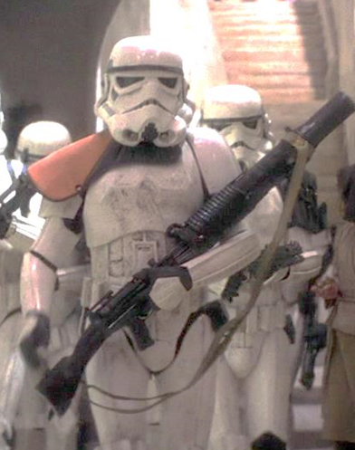
A replica Lewis Gun fits the bill for all of you. Yes, even you budding Imperial Storm Troopers out there… that’s a completely original Lewis Gun the Trooper in the picture to the right is carrying (sans ammunition drum).
This web page provides instructions on how to build one,
what's more, it includes Computer Aided Design (CAD) models in
Solidworks that allow you to print out most of the parts on
common 3D printers.
While I built the prototype using a combination of wood and
3D-printed parts, all the parts of the replica could be done
with a 3D printer. However, some of the parts are too
large to be made on the common consumer printers. It's
easier to do them in wood. Otherwise, you'll need to
split the parts in your drawing package and glue them back
together after they print individually.
To print out the parts, you'll need Solidworks or a CAD
program that can read Solidworks files. Even if you
don't have a 3D printer, Solidworks can generate standard
drawings that will aid you scratch-building one from wood.
History
In the early 1900s, an American inventor, Doctor Samuel
McClean, developed a water-cooled machine gun.
Unfortunately, it was clear that the gun violated the patents
held by Hiram Maxim
In desperation, the investors asked Major Isaac Newton Lewis if he could salvage their investment. Major Lewis saw the basic mechanism could be adapted to produce an AIR-COOLED machine gun
Major Lewis’ result was a marvel. It weighed just 30
pounds, completely loaded with a 47-round drum. It was
cooled by the bullet exiting the barrel from the inside of a
tube, which sucked cooling air in the other end.
Competing machine guns were liquid-cooled, using cloth belts to carry the ammunition that would get dirty and well in combat conditions. They were heavy… 50 pounds for the gun, 30 pounds for the tripod, a cask of coolant, etc. It took a full squad to support the gun.
 Because of these issues, conventional machine guns
were considered defensive weapons only. But the Lewis gun
needed just a gunner and another man to carry spare drums.
It could go on the offensive.
Because of these issues, conventional machine guns
were considered defensive weapons only. But the Lewis gun
needed just a gunner and another man to carry spare drums.
It could go on the offensive.Despite Major Lewis being an American, the US Army wasn’t interested. The Army had major contracts with Colt arms, and the Army’s Chief of Ordnance hated Major Lewis. So Lewis contracted with Savage Arms in the US and Birmingham Arms in Britain to have them made. The first prototypes were delivered to the Belgian Army in August 1914…the month World War One broke out.
Over 50,000 were made during WWI. The US Marines deployed to France with them…but the US Army made them give them up, since it wasn’t a “standard” gun in the US inventory (the US, instead, used the French Chauchat…a HORRIBLE weapon).
The Lewis Gun is so inextricably linked with World War One, it’s amazing to find out that THREE TIMES AS MANY were made for World War Two! To a large extent, though, they were made out of parts originally manufactured during the first war. But they were commonly used for anti-aircraft guns…in fact, it’s said that Lewis Guns destroyed more aircraft during WWII than any other anti-aircraft gun!
Lewis Gun Versions
When Britain’s Royal Flying Corps decided to start installing machine guns on aircraft, the Lewis was the logical choice. It was already air-cooled, and lighter than practically any other gun out there. With the planes of 1915, every ounce was important.But…there were things that added weight, and still weren’t needed on aircraft. The wooden shoulder stock, obviously. And the slipstream rushing by at 80 MPH could eliminate the need for the long cooling jacket (which actually worked by pushing hot air out the BARREL end. Obviously not right for forward-firing guns on aircraft.
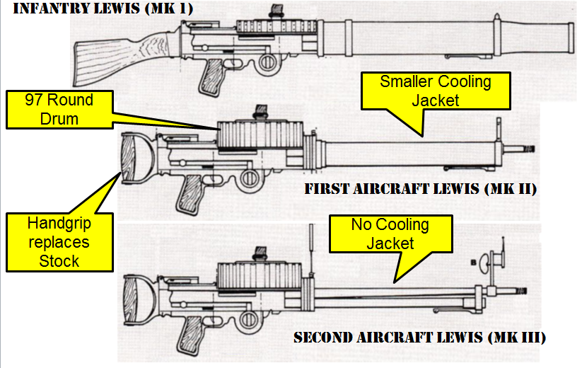
The infantry Lewis was the Mark I. The Mark II replaced the stock with a simple handle, and the big cooling jacket with a smaller one. The Mark III got rid of the cooling jacket entirely. The RFC also introduced a double-height ammunition drum that carried 97 rounds instead of 47.
Here's a diagram that illustrates the version of the Lewis:
This works to your advantage. You can make minor changes in the design to make your replica easier to construct, and it won’t necessarily be wrong.
For the reenactors and the cosplayers, I regret to say I’m not covering the Infantry Lewis in this document. However, that big cooling jacket is probably fairly easy to do with PVC pipe. What I call the "Barrel Holder" (see the construction section) can have the bracket "ears" taken off and can be resized to fit inside an available size of pipe (probably the 3" inside diameter type).
The stock will be more difficult. I have made stocks like this using a sandwich of wood. The width of the Lewis at the stock interface is 1.5 inches. Take a 1/2” piece of pine, glue a 1/2” piece of balsa to either side, and start carving and sanding. It’s really not that hard.
Replicating the Lewis Gun
There are several factors involved in replicating the
Lewis Gun. The primary one is the desired accuracy.
You have to decide if you're looking for "20 Foot", "10
Foot," "Five Foot," "Three Foot", or "Hands On" accuracy.
A "20 Foot" Lewis gun will look real to an observer 20
feet way, a "10 Foot" one at ten feet, etc.
However, this does depend on the KNOWLEDGE of the observer. Someone who KNOWS Lewis Guns will be able to tell that a "Ten Foot" replica is wrong, even twenty or thirty feet awa
When I make replicas like this, I shoot for "three foot" accuracy...basically for a visitor to step into my home office, see the replica perched there, say, "Holy S***!"...then, depending on their background, they notice the discrepancies as they come closer.Now, SHAPE-wise, I think my Lewis replica is pretty good. But you can easily take my design and "hyper-detail" it...add features that make it more and more realistic.
There are a couple of companies out there who cater to Lewis replica builders.
The Replica Plans company sells Lewis Gun plans (which include CAD files) for just $10. The pictures they have on their web page shows an excellent model. I actually found this site AFTER starting my own replica...I probably would have bought the plans.
The second replica is done by Foxflier. They sell ABS-plastic kits of the Infantry and aircraft Lewis Guns. The full kit is only $140. They even have a 7/8ths scale version to go with the 7/8ths scale CIRCA Nieuports.
So...why did I design my own?
 I wanted something in between these two
products. The Replica Plans version would require a
lot of metal working that I wasn’t capable of. The
Foxflier one is a five-to-ten foot model; it looks good on
the wing of a Nieuport, but the ABS molding softened the
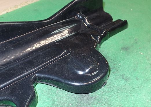
edges of everything. The picture on the right shows
the housing for the tension spring for the Lewis, with the
little "dial" that is used to keep the spring tight.
The dial is a separate piece...but notice how the molding
just blends it into the rest.
I wanted something in between these two
products. The Replica Plans version would require a
lot of metal working that I wasn’t capable of. The
Foxflier one is a five-to-ten foot model; it looks good on
the wing of a Nieuport, but the ABS molding softened the
edges of everything. The picture on the right shows
the housing for the tension spring for the Lewis, with the
little "dial" that is used to keep the spring tight.
The dial is a separate piece...but notice how the molding
just blends it into the rest.I'm not knocking the Foxflier kit. A lot of folks have done very nice guns from them, nothing keeps you from adding hyper-detail.
But I wanted a replica with sharp edges that would still look (pretty) real from just a couple of feet away.
So I started building my own replica from wood. But I bogged down after a bit. There are a lot of fine, fiddly-bits that go into making an accurate replica. And these were difficult/time consuming to do by hand, out of wood. I realized that I wouldn’t be able to get the kind of detail I was looking for, and set the project aside.
Then, right out of the blue, my wife gave me a 3D printer for Christmas.
Here was a way to DO those little
fiddly bits. I’m
a member of the Experimental Aircraft Association, and one
member perk is the educational version of Solidworks, a
very powerful CAD (computer-aided design) tool. If you’re buying
a copy outright, Solidworks costs $10,000…yet, as an EAA
member, I could download a free copy!
So I started teaching myself
Solidworks, which was kind of a slog since it’s a
professional tool, not designed to molly-coddle ordinary
mortals. As I
got better at it, I realized that more and more of the
Lewis Gun design could be printed on my Epson 3D
printer. I replaced several parts I'd already made
from wood with 3D-printed versions.
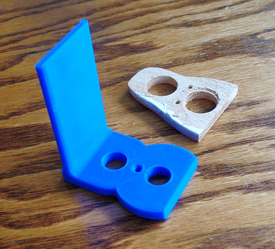 The picture to the right illustrates the
issue. These are the components that fit at the end
of the receiver where the gas tube and barrel
emerge. You can see the simple wood version I
did…next to the version generated by the 3D printer.
The vertical shelf would have had to have been a piece of
1/4” wood glued to the base piece. The 3D version is
much, MUCH better, especially as I was able to quickly
change the design as research showed what the actual piece
looked like.
The picture to the right illustrates the
issue. These are the components that fit at the end
of the receiver where the gas tube and barrel
emerge. You can see the simple wood version I
did…next to the version generated by the 3D printer.
The vertical shelf would have had to have been a piece of
1/4” wood glued to the base piece. The 3D version is
much, MUCH better, especially as I was able to quickly
change the design as research showed what the actual piece
looked like.
And it was a LOT easier to re-do parts when I found
errors. The shelf on this receiver end was too
long. I went back into Solidworks, edited the part
design, sent it to the printer, and had a new one in a
bit.
A similar mistake in wood might not have been too difficult to fix. But imagine finding, for instance, that the two holes had the wrong spacing? The whole part would have probably had to have been scrapped. Instead of just making a minor change on the computer, and re-printing it out.
So...ultimately, how accurate is my design?
Dimensions, etc. are pretty close. I have an image
of an original Savage Arms three-view drawing, which I
imported into a image tool and resized so I could directly
determine the sizes and shapes of various components.
Otherwise? Well, I’ve taken a lot of liberties in
the name of making the replica easier to build.
Primary variations have to do with the surface detail on
the receiver, the main body. I’ve taken some short
cuts there.
MOST people who see your replica, or the pictures of it, won’t be able to tell the difference.
If some aspect bugs you…well, then crank up Solidworks
and fix it. That’s the beauty of this project; it
generates a good base for doing some fine detail.
For the Solidworks
design I posted, the receiver is just a simple 1"x2"x11.5
block of wood...but two side-pieces are attached.
These side-pieces implement the surface detail I made in
wood for my model, but you sure can modify them if you
wish!
Safety
I need to mention a few things about safety.First, I designed this gun to sit on a shelf on display, NOT on the upper wing of an aircraft. If it’s going on an airplane, you need to make sure that your version is strong enough to go to the aircraft’s redline.
My version uses a short 1/4” threaded stud to hold the ammunition drum in place. This is, especially, NOT adequate for aircraft!
When I was assembling the replica, I set it on the rear handle I had to apply some pressure to get a screw started… and the lower part of the handle broke.
If you’re going to put this on an aircraft, it’s your responsibility to ensure it’s airworthy.
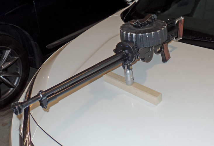
Second, understand: To your local police, there ARE no fake wooden machine guns. If you, just for a joke, strap one of these to the hood of your car and go for a drive on Saturday night, you will likely be met by a SWAT team.
You’re not likely to trigger such a reaction if you’ve got the correct historical context…the gun on the wing of your airplane, or you and your friends in WWI uniforms or at a Star Wars convention (notice many convention sites ban weapons, though, even fake ones).
Otherwise, I highly recommend you keep the replica out of the public eye. In addition, there are some countries that ban replicas like this, even non-firing ones.
Make no mistake: This is NOT a real machine gun. It’s made of wood and plastic, and can’t even chamber a bullet, much less fire one.
But you always have to be aware of people’s perceptions. The above picture was taken in my garage with the door closed. I took the replica to the airport and took another picture of it on the wing of my airplane. I had the door closed to set up the photo, then opened the door for (literally) two minutes to take the picture.
So BE CAREFUL.
On 3D Printing
One thing to be aware of is that the typical 3D printer is going to take a LONG time to print these parts. The Barrel holder alone took 14 hours. Most parts took, typically, 4-8 hours. Even as I write this, my printer is cranking out the back end of a Flash Gordon spaceship ~6 inches long...and it's going to take nine hours.So if you and a couple of buddies decide to chip in together and build several guns…well, it’s going to take a while.
If your printer has a “Generate Support” function, you’re probably going to need it. The most common type of printers can’t directly print things unless they are propped up while printing. Think of printing a bolt, with its head up. The printer can’t print on air, when it’s trying to print the bottom of the bolt head. So you have to enable the Generate Support function so it adds lightweight struts to hold things up.
When you get done, this can be a bit dismaying. You see a blob of plastic, not the finely detailed part you expected.
It’s in there…it’s just buried behind a batch of temporary struts. If you start picking at it with the point of a knife, these temporary supports pop out. It’s not 100% perfect, but I’ve been impressed at the quality of some of these pieces.
Speaking of quality, Solidworks does take a shortcut to avoid drawing smooth curves. What will happen is that you’ll get a part out, and what should be a smooth edge has facets…little flat areas that join together.
In Solidworks, click the “Option” button (the button at the very top that’s shaped like a gear) and select the “Document Properties” tab. Click the “Image Quality” option. Move the top slider all the way to “High.”
When you’re combining 3D printing and standard wood parts, things can sometimes get a bit weird. Do test prints if you’ve got somewhere with a tight fit. The sizes of the wooden dowels can vary a few thousandths from the "nominal" one-inch, and might not slip onto your printed parts as well.
But I don't have a 3D Printer!
This makes doing the parts harder. :-)However, you can still use Solidworks to generate dimensioned drawings, if you wish to scratch-build all the parts. There are companies that will take the digital parts and print them for you, but of course, that's likely to be costly.
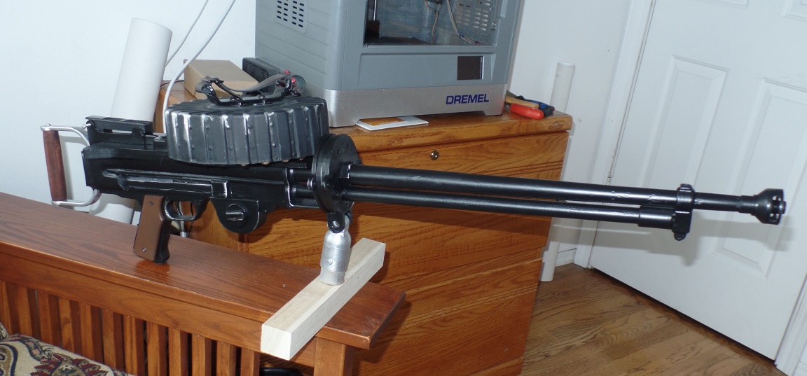
Construction
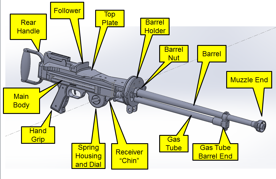
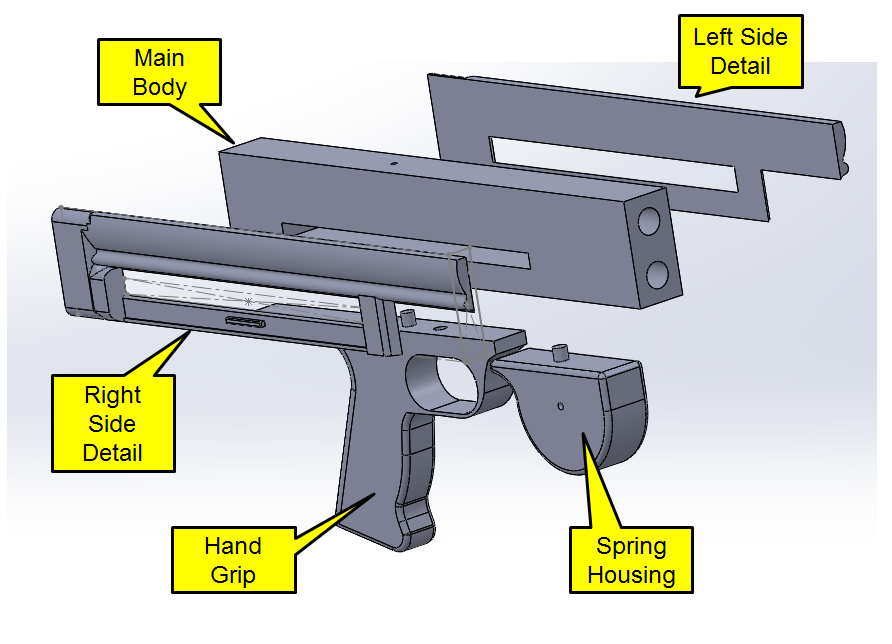
The figure below shows what I call the various portions
of the replica. The “Main Body” is the receiver, the
“Barrel” is above the “Gas Tube”, the Top Plate supports
the drum (not shown) and includes the base for the main
sight. The Hand Grip includes the trigger, and the
“Spring Housing” with its wind-up dial set right in front
of it.
The appropriate Solidworks files (and some additional data) can be downloaded here. This is a ~60 Meg Zip file and will go to your Downloads folder.
Main Body (Receiver)
The main body is the fundamental structure of the replica. It’s made of wood, 1” wide, 2” high, and 11.5 inches long. It has the pilot holes for attaching the top plate, hand grip, and spring housing. I often refer to it as the "Receiver."
The main body can be done on a 3D
printer…but it’s 11 1/2” long. That’s too
long for my printer.
Since it is the fundamental structure, I used wood. The Main
Body is 1” wide, 2” high, and 11.5 inches long. Note the
slot…this is where the bolt slides, and the charging
handle would be installed.
While I made the hand grip and the spring housing from
wood as well, I have included the Solidworks files. You can get
the shapes and dimensions from them. Locating
holes are provided in those Solidwork parts, although
of course, if you’re making them from wood, just put
the holes where necessary to get it to fit.
The spring housing shows a bit of filet on top…this is
accurate; the housing is really a separate component.
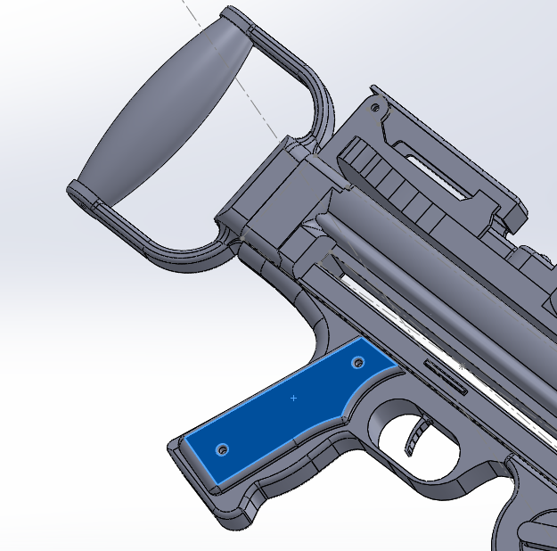
Included in the package are “Hand Grip Right” and
“Hand Grip Left”.
These are thin plates that attach to the hand
grip. On
the actual gun, these would be thin wood, shaped to
smooth the grip to the user’s hand.
Detailing the Main Body
The standard Lewis has shaping on the sides, not just the slab sizes that the 1x2x11.5 wood block provides. For one thing, the width of the body has to be 1.5” in back, to fit the rear grip. Looking at the basic design, there’s a “bulge” at the top of the receiver basically around the extended line of the barrel; this bulge blends into the 1/4” thickness that’s added to the end of each side.
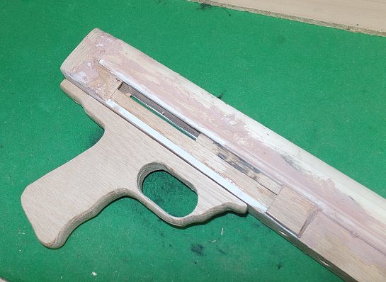
I did all this shaping manually, using segments of
dowels, pieces of wood, and some plastic angles.
This picture shows the in-process look....I did a lot
of Bondo work and sanding to get things really smooth.
What I did for the Solidworks model was design the detail as an overlay, to be attached to the sides of the main body. You see those back on the Main Body illustration. These can be printed, then glued to the main body to give some semi-realistic shaping to the sides of the main body.
“Semi-Realistic.” The design is
evocative of the actual Lewis, but not perfect. Feel
free to experiment and improve.
5.1.2 Attaching the Barrel and Gas Tube to the Main Body
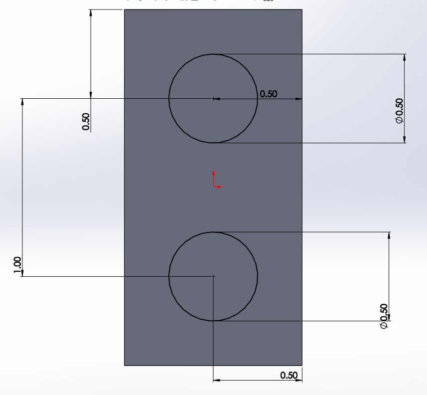
The main body includes bored holes on the end for attaching the barrel and gas tube.The 1/2” holes in the main body match the holes in the receiver end, while the 1/2” long extensions of the barrel and gas tube spacers insert into these holes. The barrel holder slides over the end of the spacers, and the spacers include 1/4” holes for dowels to connect them to the main barrel and gas tube.
Here’s the dimensions of the holes that need to
be bored into the end of the main body:
However,
this
is VERY awkward to do. I
made my main body out of two 1/2” pieces of wood, and carved
out SQUARE holes using the table saw:
These are pretty easy to do with the table saw. Use a scrap piece of 1/4" wood and one of 1/2"....you can set up to cut, for instance, the bottom part of the top slot, then stick the 1/2" spacer in to automatically cut the top part. You just maneuver the block around a bit to take out the rest.
The slots don't go through the entire body...just for a few inches. My Solidworks part drawings of the shafts show them as 2” long; you can certainly cut the holes longer into the main body if you wish.
By the way, after you glue to the two halves together, use the table saw and saw off just enough of both ends so they're even and straight. It'll make the handle and the receiver end fit better.
Barrel/Gas Spacers
This image shows how the barrel and the gas tube actually attach to the Main Body. The shafts on the spacers go into the body through the "Combined Fillet Rings” and the Receiver End; the Receiver end actually has a space and hole for a countersunk #4 screw to attach it in place.
The Barrel Holder includes a provision for a countersunk #6 screw between the flanges at the bottom. The screw runs through the holder into the gas tube spacer. Those longer flanges are the main attachment of the replica to the mount, by the way.
You’ll note an item called “Combined Fillet Rings”. These provide a fillet for the tube spacer join with the Receiver End. You could do this Bondo or similar, but this is easier.
Barrel and Gas Tube Spacer Construction
Now: I made the barrel and gas tube spacers on a lathe. I’ve included Solidworks models for these, so you can probably far more easily print them out than go buy a lathe. If I were to build a second Lewis, I’d do it this way.
HOWEVER: The attachment of the spacers to the body,
and the barrel and gas tubes to the end of the spacers, is
probably the most critical portions of the design, as far
as the STRUCTURE are concerned. The barrel and the
gas tubes themselves attach to the spacers using short
1/4” dowel pins.
This is adequate for a ground display, or running around in trenches with re-enactors, or marching through a convention with your fellow cosplayers. I am, though, skittish about this for replicas intended to be mounted to actual aircraft.
I think the turned wood versions are stronger than a 3D printed version would be…but you’re still stuck with the interface between the spacers and the tubes. I think epoxy probably works better between the wood spacers and the wood barrels, vs. a plastic 3D printed spacer and the wooden barrel/gas tube.
If you’re intending to mount this on an aircraft, come up with ways of beefing up this interface. Possibly use a 1/4” steel rod into the main body, through the inside of the spacers, and an inch or three into the barrel and gas tubes.
There are other options, too, which I’ll discuss in the next section.
By the way, these spacers and the barrel/gas tube require
a hole drilled into the ends dead-center to take the dowel
that connects them to the other portion. There are
three Solidworks “Drill Guide” parts….one for 3/4”, one
for 1”, and one for 1 1/4”. These are like stool
caps. They slide snugly over the end of the wooden
dowels, and including teeny tiny hole dead center.
Use that for drilling into the exact center of the rods.
Barrel and Gas Tube
While I include a Solidworks version in the package, the “Gas Tube” is a 3/4” wooden dowel, and the barrel starts as a 1-inch dowel, tapered from one inch at the receiver end to 5/8th at the muzzle.
One of the classic features of the Mark III Lewis is that
tapered barrel. I love the look, and actually bought
a small wood lathe specifically so I could taper a dowel
to get that look (I’m always looking for an excuse to buy
tools). This figure shows the stock barrel system.
By the way, see the nut at the base of the barrel?
Completely non-functional. Just glues in place as a
bit of additional detail.
The gas tube itself is just a straight 3/4” dowel, and it sockets into the Gas Tube Barrel End. The Barrel End also slides over the tapered barrel, and include a little socket on top for the front sight.
The tapered barrel is stock to the Lewis Gun. However, not everyone is willing or capable to taper the barrel.
If that’s the case, you have two options. The first is to just NOT taper the barrel. Run a 1” dowel for the barrel and a 3/4ths inch one all the way from the front of the Main Body to the muzzle…get rid of the spacers entirely. You’ll have to figure out how to add the 1/2” extensions to go into the main body, but you’ll have solid rods all the way out.
It doesn’t look “Right”…but most people won’t be able to tell. You’ll need to resize the Gas Tube Barrel End to match the 1” dowel, as well design a new muzzle end. Not a big issue.
The other option? Go with a Mark II Lewis Gun.
In this case, the 1” tapered barrel is replaced by a 3/4” fixed-diameter wooden dowel. It glues onto the end of the 1” barrel spacer just like the tapered barrel. The PVC tube as the jacket hides the change.
The modified Barrel Holder “Barrel Holder Mark II” included in the Solidworks ZIP file, as are the 3/4” barrel and the jacket end. Please note that I have not tested this…I haven’t printed out the modified barrel holder. So you might have to make some adjustments.
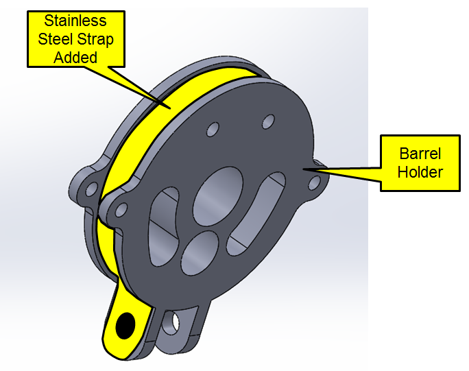
A Note on the Barrel Holder
The Barrel Holder for the Mark II and Mark III
are pretty historically accurate; I copied the
design from an original Savage Arms drawing.
It includes a pair of flanges at the bottom to
allow the gun to be attached to a solid
mount. This is probably how your replica
would attach to an airplane. There are
additional flanges on the sides where clamp
handles were attached.
There’s a lot of load on the Barrel Holder. I’m not too confident that a 3D model made from plastic will be up to the job on an airplane.
Alternatively, you could have this machined out of aluminum (or 3D printed from metal). Even a wood replica might be stronger.
One possibility is shown below. Wrap the channel of the barrel holder with a stainless steel strap, leading down to both mounting holes. This way, the strap is there to take the load.
One more factor about the Barrel Holder: When you’re combining 3D printing and standard wood parts, things can sometimes get a bit weird. You’ll size a 1” thick dowel in Solidworks…but the one you pick up at Lowe’s might be 1.04”, even 1.1” in diameter. So those holes in the barrel holder might need to be enlarged slightly. You can usually start a print, then cancel it after it has established the basic disk, then use the part to check whether it’s compatible with your dowels.
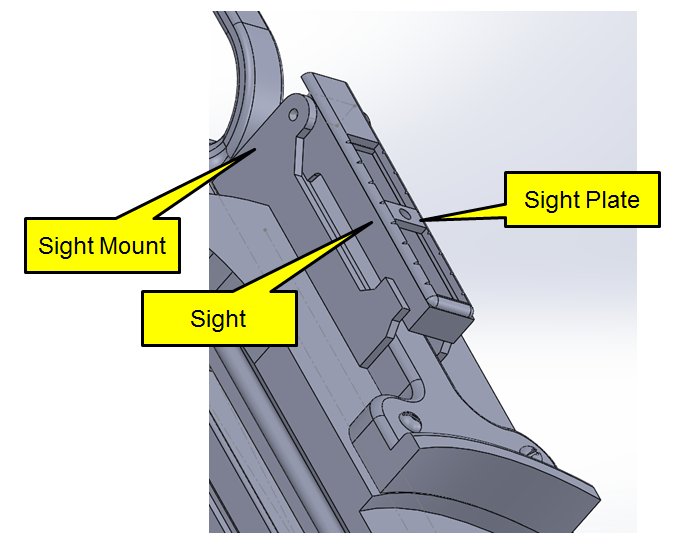
Top Plate
The Top Plate sits on top of the Main
Body. There are a line of holes in the
mail body; these line up with the centerline
of the Main Body. The top plate should
be positioned so that the back edge of the
sight mount lines up with the back edge of the
main body. The design includes a sort of
T-Shaped “Follower” that helps back up the
drum.
Doing further research, I think this
“follower” was actually one-piece with the top
plate. But one of the #6 countersunk
screw holes go through the top plate right
about in the middle of the “Follower” so that
makes things easier to screw together.
Plus, the 3D-printed follower will have better
detail than if a single part.
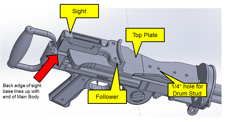
In addition to the mounting holes for the top plate, there’s a 1/4” hole that designed to take a short piece of 1/4” stud. The bottom of the drum is threaded to match, and that’s how I hold the drum in place.
This will NOT work for anything but a static display. If you’re going to carry it on an aircraft, or even use it in reenactments, you’ll need a more sturdy attachment.
The Star Wars cosplayers don’t use a drum, and the stock Lewis Gun attachment post is there, instead. Replace the 1/4” hole with a 1” diameter post, about 1 inch high.
The top plate includes the base for the aft sight, The sight itself is separate, and uses a #6 machine screw to allow it to pivot. The file also includes a “Sight Plate”; this simulates the ranging graticule. Just superglue it atop the loose sight piece.
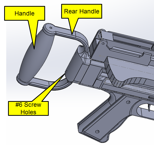
Rear Handle
The aircraft Lewis Guns replaced the
wooden stock of the infantry model
with a small hand grip. I
debated trying to build this from
aluminum and wood, but by that point,
I was getting confident enough with
Solidworks that was able to tackle
it. It’s four inches from the
top and bottom insides of the grip…
you’ll need a length of 3/4” or
7/8” dowel. In my case, having a
lathe, I actually turned a nice
double-tapered grip. The hole in
the grip is sized for #6 screws.
Drum
The Solidworks package includes a drum…but I didn’t print it out and use it. It’s too large for my 3D printer.
The drum kit I purchased from Foxflier () was MORE than
adequate. I needed to make a
bracket for the top of the drum,
but it did come out nicely.
They sell the drum alone for
$35. It’s the large aircraft
drum, but Infantry users can just
slice it like a bagel to simulate
the 47-round drum.
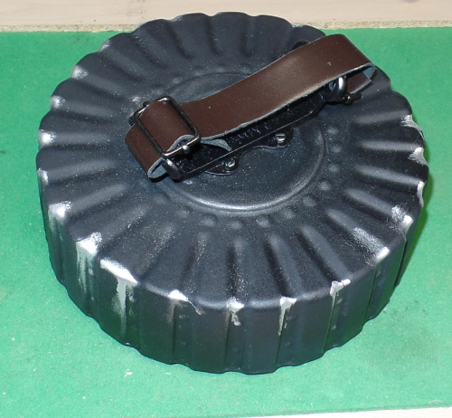
Lewis gun drum handles varied in
design, but most included a
leather strap like my picture
shows. I bought some buckles
and other hardware at a craft
store.
Finishing
One thing you’ll find is that wood surfaces tend to show their grain through any paint that applied. So you’ll need to apply several coats of primer, sanding things down to try to smooth out the grain. That's one advantage of the 3D printer output, the plastic paints very well.
I love working with oak (it’s
tough and doesn’t splinter), but
it’s got a hellaciously deep
grain. Woods like pine and
poplar finish better, but, of
course, aren’t as strong.
I have a preferences for using
stock paints on dummy guns like
this. The trouble is, it’s
impossible to find a good
“gunmetal gray”. I found a
dark gray primer that was actually
pretty good, but it had a matte
finish. Matte gets that way
by having a rough surface; to me,
it doesn’t simulate metal very
well.
What I’ve been doing is painting
with GLOSS black, then spraying it
with a clear matte finish.
It still has a touch too much
shine to it, but does look a lot
like smooth metal.
As a crowning touch, I use a
product called “Rub ‘n Buff,” in
silver. This is, essentially,
paint in a paste form. Put a
TINY amount of it on a fingertip,
and rub any bit of
protrusion. This does a
beautiful simulation of paint
rubbing away. Do it on
several outside edges, the area
around the trigger, etc.
It’s easy to go too far (that’s
what happened with that drum
picture above) but it does make
things really snap out.
Keep in mind that the rear grip
was basically a bent metal
strap…that’s why it’s painted
silver on my replica. The
vertical dowel would be wood…as
would the left and right hand
grips.